Crisis Lift
A modular, 3D-printed quadcopter airframe with interchangeable payload pods, aimed at first-responder use.
- Status
- Printed, not flown
- Period
- Jan–Sep 2025
- Discipline
- Hardware
- Reference
- KL-M2
Overview
Crisis Lift was a project to explore affordable aerial tools for first responders. The idea was a quadcopter airframe that could be printed on a desktop 3D printer, assembled with common hardware, and repaired by swapping one part instead of replacing the aircraft. Mission equipment would ride in interchangeable pods under the body. I led the project: I set the requirements, directed the design through several rounds of changes, printed the parts and worked through the assembly. The detailed CAD modelling was done by an outside freelance CAD designer working to my direction.
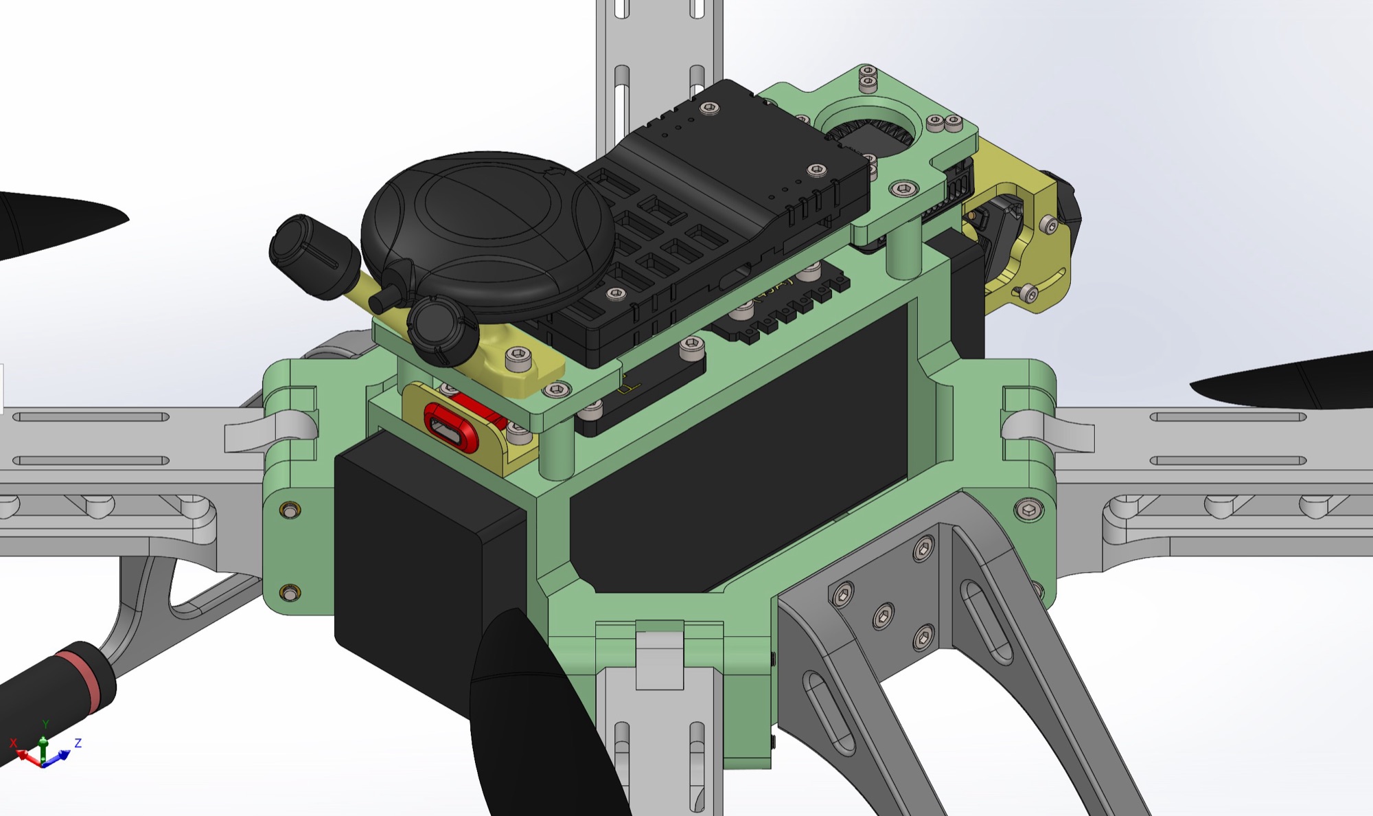
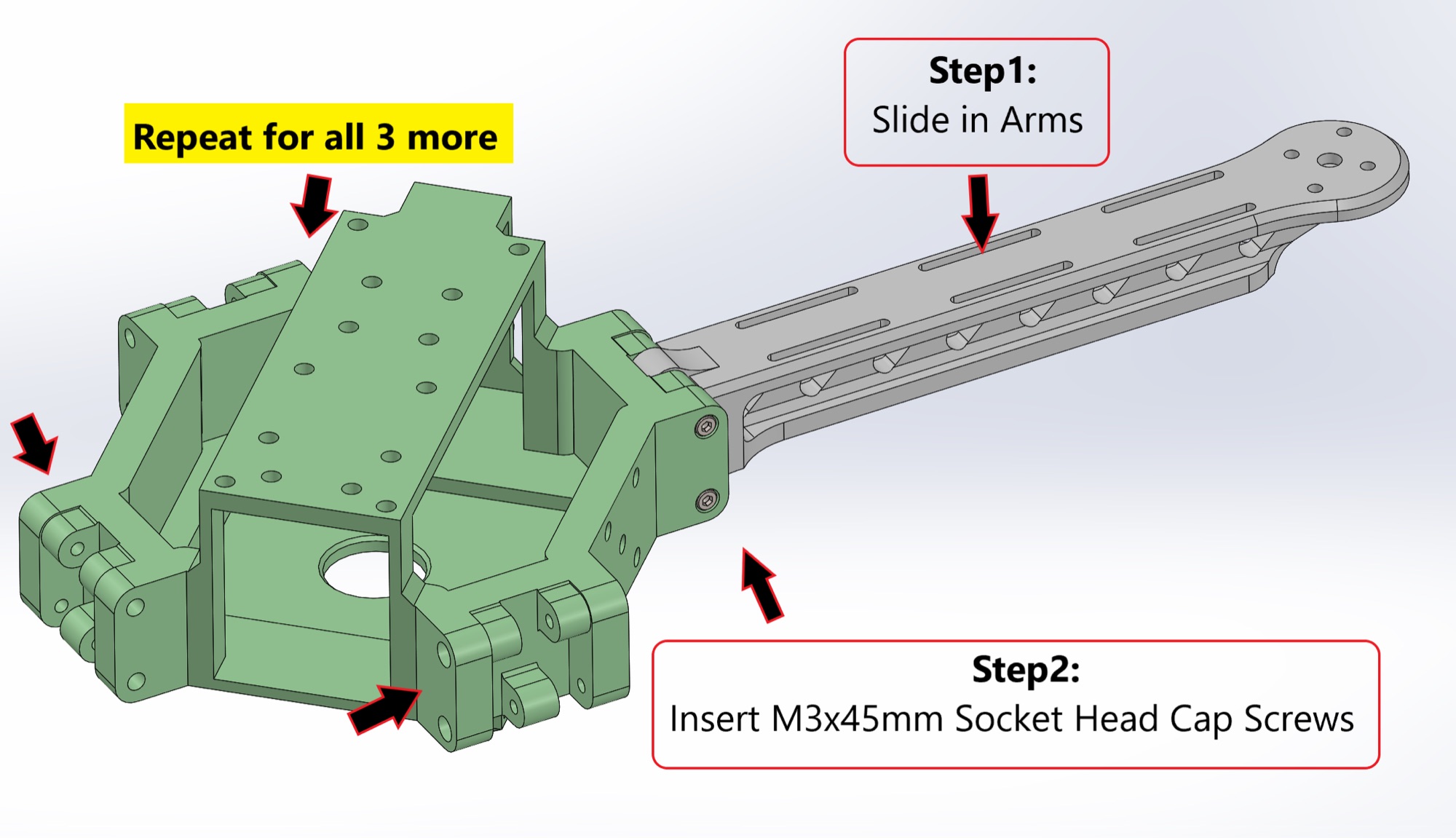
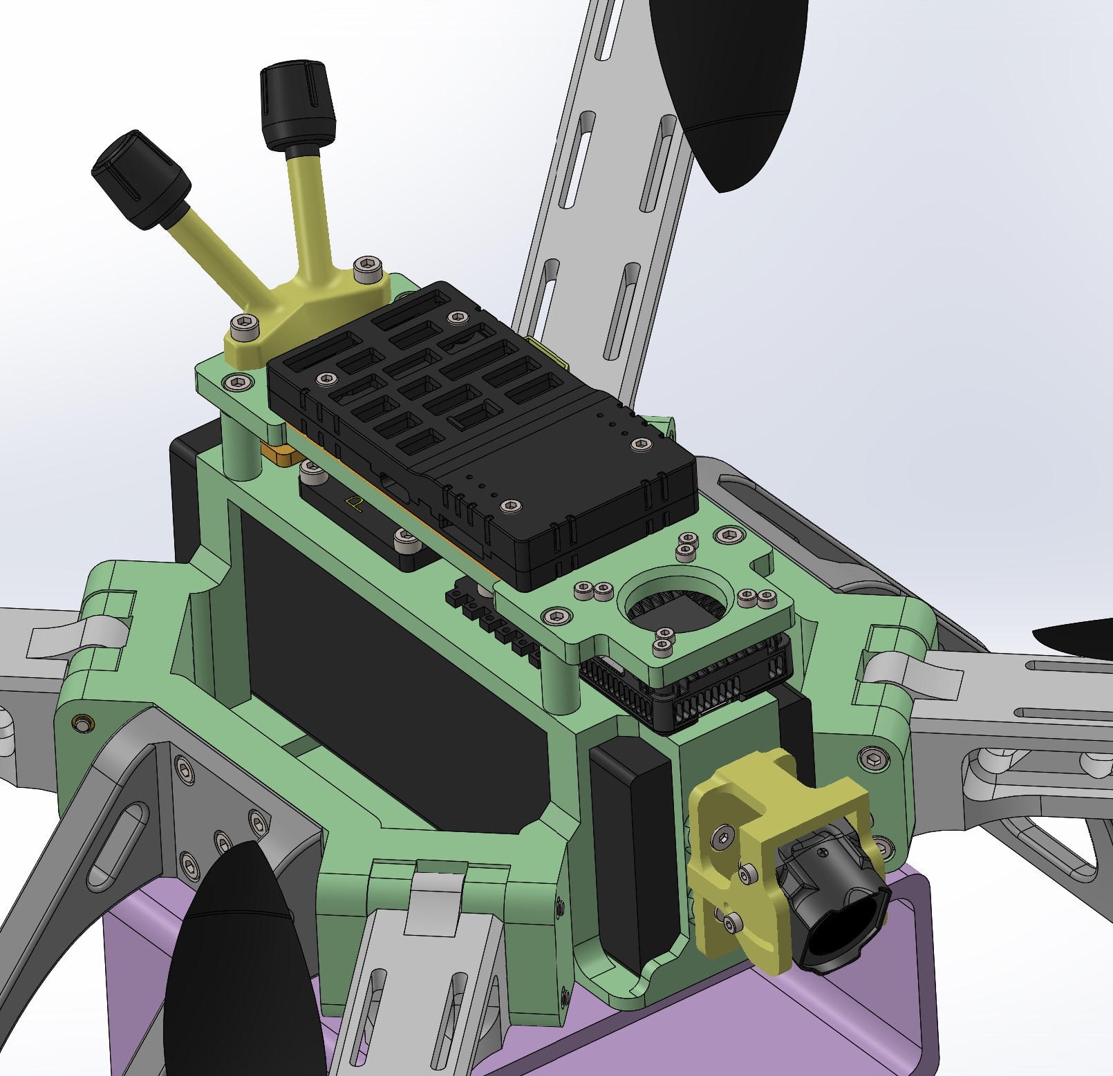
The airframe is built around a central chassis that holds the battery and electronics. Four arms slide into sockets on the chassis and are each fixed with M3 x 45 mm socket head cap screws, so a damaged arm comes out without disturbing the rest. Threaded M3 inserts in the chassis take the landing gear, which uses curved legs with soft pads as shock absorbers. Under the body, a rail and a two-part clasp form the attachment point for payload pods. Smaller printed parts mount a GPS module, a digital video air unit and its camera, a USB-C charging port, and a battery cover with an antenna holder.
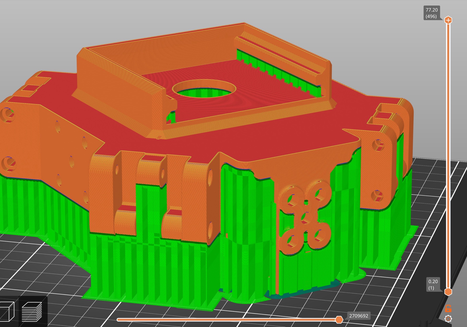
Most of the work was iteration between CAD and the printer. The archive holds CAD views of the electronics bay, motor wire routing and the payload rail, along with slicer previews showing how the chassis was oriented and supported for printing. Parts were revised between rounds. A later chassis file added a radio mount, and a GPS mount and a battery cover with antenna holder are dated a month after the first part set. The build order was then written up as a 13-page assembly manual with annotated steps: inserts first, then arms, motor mounts and landing gear.
The project reached a complete printable part set, printed airframe parts and the assembly manual. Affordability and repairability were design intentions that shaped the part breakdown, and I did not measure either. The substance of the work was practical: splitting a structure into printable pieces, fixing slide-in joints with common hardware, and producing documentation that lets someone else build the same thing.
Specifications
- The print set has 13 distinct part files in 3MF and STL formats, covering chassis, arms, landing gear, payload rail, clasp and mounts.
- Each of the four arms slides into the chassis and is fixed with M3 x 45 mm socket head cap screws.
- The landing gear is fixed with M3 x 8 mm screws into threaded M3 inserts set in the chassis, and ends in soft pads that act as shock absorbers.
- Payload pods attach through a rail, a rail block and a two-part male and female clasp under the body.
- Dedicated printed mounts hold a GPS module, a digital FPV air unit camera, a USB-C charging port and an antenna.
- The assembly manual runs to 13 pages and documents the build in annotated steps.
- Core part files date from March and April 2025, with CAD iteration starting in February 2025.